
Guide: Vallox Digit Ventilation to Home Assistant (Part 1/2 – hardware)
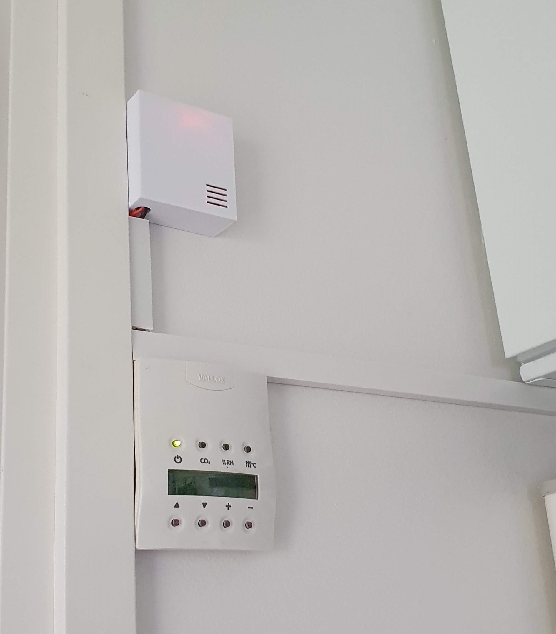
I have four years old basic Vallox 121SE ventilation machine doing the ventilation of my house, controlled by small display with few buttons. By doing some research, it seems like there’s a RS485 bus running from machine to the controller.
After googleing a bit, I even found the protocol specifications and some DIY stuff related to it, so I thought it would be nice to have it connected to Home Assistant as well. So, if you are having a Vallox ventilation machine (I have Vallox 121 SE, but this should work with any Vallox with Digit protocol) this guide is for you.
This guide gives you a briefing how to integrate your Vallox Digit protocol ventilation machine into your Home Assistant software through MQTT.
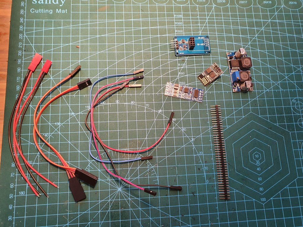
Materials needed
- 1x ESP-01 + Level converter (Amazon.de, AliExpress)
- 1x RS485 to TTL (with automatic flow control) (Amazon.de, AliExpress)
- 1x DC-DC Buck Converter (Amazon.de, AliExpress)
- Dupont wires (Amazon.de, AliExpress)
- Pin headers (Amazon.de, AliExpress)
Optional (for easier installation):
- 2x Servo lead cables (Amazon.de, AliExpress)
- 1x JST Pigtails (female and male) (Amazon.de, AliExpress)
Software & flashing:
- Arduino IDE and flashing adapter (e.g. ESP-01 UART) (Amazon.de)
- Software
The build – overview
ESP-01 works with 3.3v (signal and voltage) and RS485 is a serial BUS with 5v. We therefore need the level converter (luckily there’s a ready made alternative that fits directly in the ESP-01).
Also Vallox is outputting 24v as voltage and we want to power ESP-01 & RS485 module directly from it without using an external power supply. That’s where buck converter comes handy.
So, RS485 module converts the signal provided by Vallox into a TTL signal understood by ESP-01. Buck converter lowers the voltage to 5v that powers the ESP-01 (through level converter) and RS485 module.
Keep on reading if you want to see step-by-step guides 🙂
The build – soldering
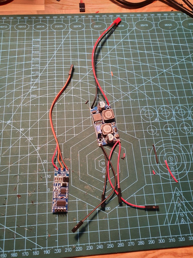
Start by soldering pin headers into RS485-TTL converter.
Cut two (preferrably black & red) dupont wires into two and solder those into buck convert output (red into + and black into -).
Solder JST connector (male) into buck converter input (red into + and black into -).
Cut one of the servo cables from the root of female head and solder the wires into RS485 A, B and GND (red A, orange B and brown GND.. of course depending on your cable colours, but just remember the correct order later).
The build – ventilation connections
Cut the second servo cable from the root of male head and take multimeter, cutted servo cable, JST male cable and buck converter with you to the Vallox ventilation unit and unplug the ventilation machine from main power.
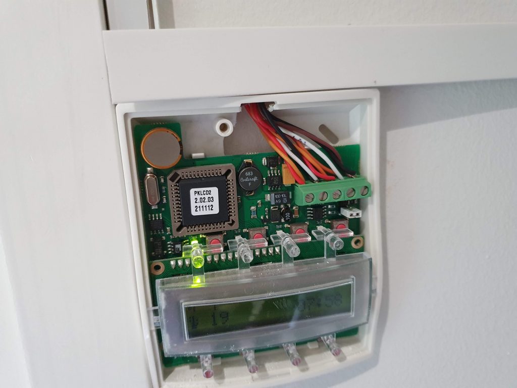
Now open the ventilation control unit and open it (screw is behind the top plastic covering). After opening the cover, unscrew two left connectors from the top right corner and connect power (JST) cables into it with the existing ones. Red to left and black to the next one (verify + and -). Tighten the two screws.
Next connect the signal cable (servo). Unscrew next three cables and connect red (A) to left, orange (B) to middle and black (GND) to the right. If having different colors, just be sure that connections matches to the solders of RS485-TTL connector. Again, ensure A, B and GND from the machine.
You can now close the ventilation controller.
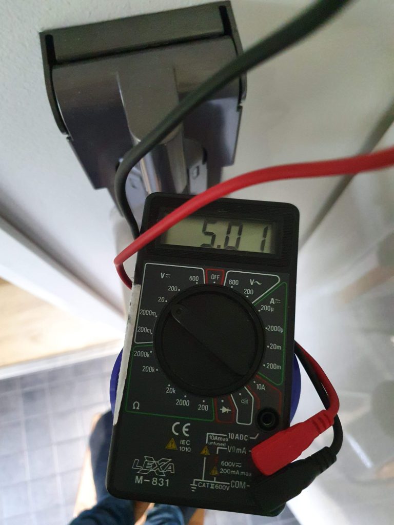
The build – setting the buck converter voltage
Next we need to set the buck convert to proper voltage. Vallox machine is outputting DC 24V and we need to convert it to 5V.
Connect your buck converter to the JST female you just installed. Take your multimeter and set it to 200V or 20V mode. Connect your ventilation machine back to main power and turn it on. Now the red (or blue) light should also be lit on your buck converter.
Measure output voltage from the buck converter and screw the small screw until you get 5V reading on the multimeter. Now we have proper voltages.
Unplug the buck converter and head back to finish your build.
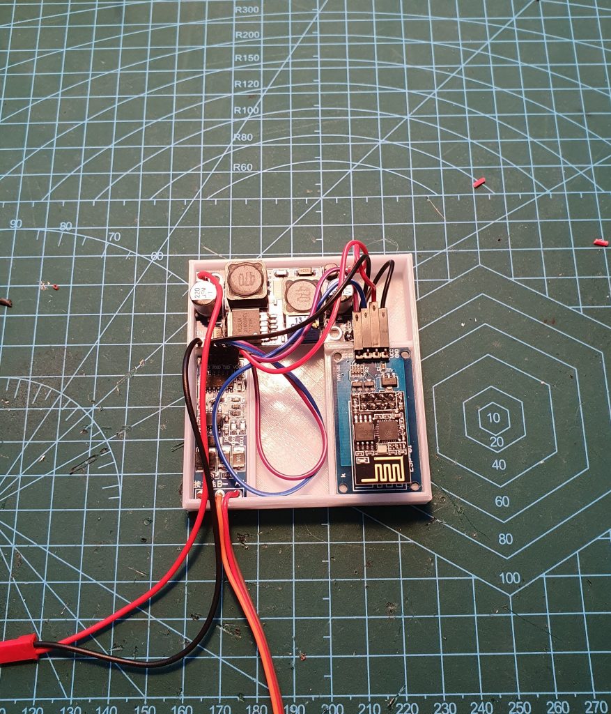
The build – finalizing electronics
Now let’s finalize the hardware.
Connect output + (red) dupont from the buck converter into RS485 module VNC pin. Connect output – (black) dupont from the buck converter into RS845 module GND pin.
Now do the same for the ESP-01 adapter. Connect another output+ (red) dupont from the buck convert into ESP-01 adapter VNC pin. Connect output- (black) dupont from the buck converter into ESP-01 adapter GND pin.
Now connect new dupont cable from RS485 RX pin to ESP-01 adapter RX pin. Same to the TX pins.
All done! Next step, software.
Flashing the software
I presume that you have basic knowledge of Arduino and flashing software. If not, you can find tons of information from the google.
To flash ESP-01 you can use e.g. this adapter.
Software to be flashed can be downloaded from https://github.com/kotope/valloxesp
Before flashing, be sure to set following values into valloxesp.h:
- ota_password (password used for OTA updated) (optional)
- ssid (your wifi SSID)
- password (your wifi password)
- mqtt_server (your mqtt server address)
- mqtt_username (your mqtt server username)
- mqtt_password (your mqtt server password)
When successfully flashed the software, just connect the ESP-01 module into ESP-01 adapter. All done.
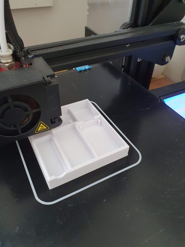
Printing the case (optional)
Of course to make the installation of the module good looking, a case should be created. Since I have a 3D printer I’ve designed a 3D model to fit all the parts inside. You can get the model from https://www.thingiverse.com/thing:4579311
If you do not have usage to a 3D printer, you could try to fit the parts inside some generic plastic cases. Go and experiment 🙂
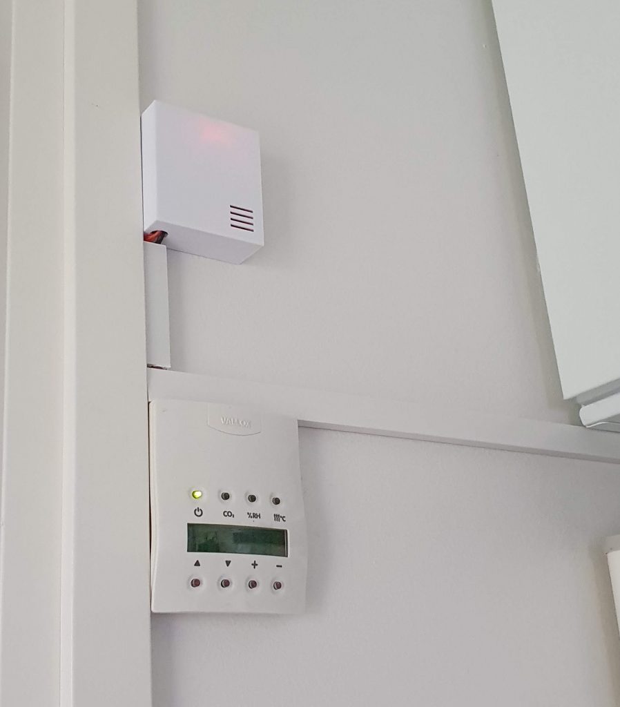
Installation
Now that everything is ready and we do have everything set up in a case, it’s time to do the final installation.
You should now have two connector already hanging from the ventilation control unit. Just connect your power (JST) and RS485 (Servo) into the hanging connectors and you’ll be ready to go.
After connection, you should see events dropping into your MQTT gateway.
If having issues, feel free to drop a comment below and I’ll try to help as much as I can.
Thanks for the guide. I’ll write in english because your blog is in this language. I think that ability to connect to (non-smart) HVAC equipment is the difference between playing around and actually useful home automation. Even though I was unable to get this working with Wemos D1 mini today I will get the same hardware as you and connect to my Vallox 096SE using these instructions.
Thanks for the feedback.
I don’t know if Wemos D1 is 5v compatible on signal levels. If not, probably will cause issues on RX signal by not getting any packets.
You could try sending ‘{ “DEBUG”: true }‘ (json message) on the “vallox/set” topic through mqtt.
After that, if packets are received, you should see something like following on MQTT pipe:
vallox/debug {“packetRecv”:”01 21 11 00 a3 d6 “}
vallox/debug {“packetRecv”:”01 11 21 a3 01 d7 “}
vallox/debug {“packetRecv”:”01 21 11 00 71 a4 “}
vallox/debug {“packetRecv”:”01 11 21 71 00 a4 “}
vallox/debug {“packetSent”:”01 22 11 00 08 3c “}
If you are receiving packets, most probably the protocol is not 100% compatible with your ventilation unit and the code needs some tweaks.
If not, then I’d suggest either by putting 5v level converter between Wemos and RS485 module or using the same components I did.
Please keep me posted about your progress as well if possible 🙂
I already disconnected Wemos from Vallox for now because I have less sophisticated control running. It is Pi with USB RS485 converter running HA that just sends shell commands to control the speed of the fan based on co2 and humidity sensor readings in the house. Nevertheless once you get used to automatic air conditioning it is hard to go back to full manual.
I did try to send some messages from my PC though but I was unable to receive any packets. It is possible that my USB serial stick is broken though. MQTT is up because I saw my debug command with MQTT Lens and I am also able to ping Wemos.
I will update my progress once I get some new toys from China or if I get this Wemos working properly. Thanks for the help with troubleshooting also!
Hi. Do you have any project page on your on how to setup pi with rs485? I got already pi and rs485 usb adapter.
Hi,
Unfortunately I have not done RS485 integration with RaspberryPi so can’t help on that matter 🙁
Also in my opinion, it would be kind a overkill to put raspberry pi just for RS485.
If you are using home assistant with that rpi, I’d suggest to put it just as a headless server and create a esp8266 based RS485<->MQTT adapter with these instructions 🙂
EDIT: Sorry, I think your comment was meant for Sami.
Short answer: Nope.
Long answer:
What I did is simply use bash commands. I use HassOS (Home Assistant) but they should work for any Linux type of OS. USB type RS485 adapter doesn’t require much configuration. You can experiment in console.
For example:
echo -en “\x01\x22\x20\x29\x01\x6d\x01\x22\x10\x29\x01\x5d\x01\x22\x11\x29\x01\x5e” > /dev/ttyUSB0′
That will set the fan on speed 1. Reading the manufacturers communication protocol multiple times was necessary for me to learn how to command the unit.
I would send the command twice because Raspberry seemed to be lagging a lot with serial communication on. I also had sensor reading abilities but they stopped working after some Home Assistant updates. Serial sensor in Home Assistant seems to be half finished and not working at all for me. Again I would also recommend something else for this purpose.
For reading sensor data I used xxd-command:
xxd -l 0x100 -g 1 /dev/ttyUSB0
The explanation for bytes you see is explained in protocol.
I promised to report my progress and now is a good time. Today the RS485 to TTL converter arrived and I plugged it between my Wemos and Vallox since ESP-01 is yet to arrive. Turns out the 5VDC voltage from Vallox bus was too much for Wemos because the communication started working immediately. Home assistant is now receiving all the data and I was able to change fan speed. Needs some further testing but looks great so far!
Do you have information if this will also work with Vallox Digit2 SE? I have received both bus specifications from Vallox but have not yet started the project to implement controlling my Digit2.
Both are using same control panel but I have the impression that the protocol is a bit different
What I’ve heard also is that Digit2 might have a bit different protocol, but can’t be sure since don’t know anyone that has the device.
Anyhow, most probably only just minor modifications are needed to make it work with it.
Do you have the “other” digit2 protocol? If so, could you send it and I’ll have a look and could even do the implementation (no possibility to test though, since I don’t have such a device myself). 🙂
Sure I can share the protocols. Can you send me s email? I did not locate yours here on this page…
Thanks for the specifications!
I did a quick comparison between those 4 and 5 sensor machines (vallox digit2), and it seems that it should work with the same software.
There’s an extra sensor in your machine that is not implemented in my code and also fireplace activate was missing from the specifications. I think the fireplace missing is a bug in specifications though, since other values were there in same program variable and no other message to enable fireplace mode was found.
I have now finally implemented this to my Vallox Digit 2 SE. Fully according to your instructions and it is working great!
Only thing I am missing is the humidity sensor reading. Currently showing constant -999. Will have to check what is the problem with that.
Thank you for very detailed instructions and great project!
Good to hear it works 🙂
As I said on some other comment, I don’t have RH sensor myself so the RH feature is not tested at all.
I can try to make it work, if you can take some debug logs and send them to me?
You can enable logs by sending ‘{“DEBUG”: true}’ message to ‘vallox/set’ topic. After that messages to ‘vallox/debug’ should start dropping.
20-30 packet messges should be enough to find out the issue 🙂
Of course if you are familiar with the Arduino and programming you can fix it yourself. If you do that, please make a pull request to my repository so that we get the working RH into master branch aswell.
Finally got the time to log the debug messages. These are the received values:
“packetRecv”: “01 11 20 2c 00 5e ”
“packetRecv”: “01 11 20 2b 00 5d ”
“packetRecv”: “01 11 21 71 00 a4 ”
“packetRecv”: “01 21 11 00 71 a4 ”
“packetRecv”: “01 11 21 a3 0d e3 ”
“packetRecv”: “01 21 11 00 a3 d6 ”
“packetRecv”: “01 11 21 35 91 f9 ”
“packetRecv”: “01 21 11 00 35 68 ”
“packetRecv”: “01 11 21 29 0f 6b ”
“packetRecv”: “01 21 11 00 29 5c ”
“packetRecv”: “01 11 21 a3 0d e3 ”
“packetRecv”: “01 21 11 00 a3 d6 ”
“packetRecv”: “01 11 21 71 00 a4 ”
“packetRecv”: “01 21 11 00 71 a4 ”
“packetRecv”: “01 11 21 a3 0d e3 ”
“packetRecv”: “01 21 11 00 a3 d6 ”
“packetRecv”: “01 11 21 35 91 f9 ”
“packetRecv”: “01 21 11 00 35 68 ”
“packetRecv”: “01 11 21 29 0f 6b ”
“packetRecv”: “01 21 11 00 29 5c ”
“packetRecv”: “01 11 21 a3 0d e3 ”
Humidity measured is roughly 27% during this trial.
Hi and thanks,
Seems like this log misses all the information about RH. If it’s possible, could you take even longer log and send it through email creatingsmarthome [at] gmail.com ?
However, even without further logs, I noticed that the RH variable is different than the specifications say. So by fixing that it might start working. I’ll try to make it today and if you can test it some day it would be great 🙂
Hi,
I corrected the RH feature and added also support for second RH sensor.
It’s currently in a separate branch until tested with a machine that has RH sensor(s) installed.
If you could, please flash new firmare to your ESP8266 🙂
Branch name is ‘feature_rh’ and you can clone the full branch with
git clone --branch feature_rh https://github.com/kotope/valloxesp.gitI wonder if this level converter https://www.aliexpress.com/item/32582870692.html does the same as the level converter you are using? If I got it right, the level converter lovers 5v -> 3.3v for the power, 5V->3.3v for RX and 3.3v->5V for TX..?
Hi,
You are absolutely right, level converter needs to be bidirectional. The item you linked should work fine, however, please note that for that you need to have separate 3.3v and 5v lines i.e. you need to “power” both sides of that converter with proper voltages. If using some premade ESP8266 dev boards (e.g. Wemos D1), you have those power levels already available so should not be a problem.
The reason I chose ESP-01 module was because it was basically plug-and-play, no need to do any extra wirings 🙂
Thanks for the extremely comprehensive tutorial!
I’m just getting to know Home Assistant and originally one use cases I had in mind when setting up the server was to use a simple relay to control the “fireplace booster switch”.
Then as I was searching the pinout from the user manual, I found that the controller supports RS-485, and after some googling I stumbled across this tutorial. I’m lacking some bits and pieces of the required setup, but this surely saved me countless nights of tinkering! Thanks in advance, I’ll report how I manage to get this working.
Thanks for the feedback 🙂
I’d be glad to hear how it works after you get it done.
What model of Vallox you have? I could add it to “tested devices” list after you’ve finished your build.
I have a Vallox Digit SE with an older control panel. Managed to install all the components inside the control panel itself. See the photos:
https://user-images.githubusercontent.com/5614724/119680902-46d2a780-be4a-11eb-92de-95ed7706ea3f.jpg
https://user-images.githubusercontent.com/5614724/119681208-87322580-be4a-11eb-888c-62a7b5bee0ac.jpg
https://user-images.githubusercontent.com/5614724/119681271-96b16e80-be4a-11eb-8de3-15ecf8f85f19.jpg
Wow, very nice and clean installation!
Maybe I’ll do the same some rainy day 🙂
Just finished the setup and all working OK. Thank for your help and work with this one! Only thing i am not sure is “Ventilation Summer mode” When i turned the power on, first state was “Turned on”, as i think it should be. But then around 5 minutes later, it when to a off state and staying there.
Also now during writing this one, i noticed that “Ventilation Motor out” went from On to Off and then back On. Not sure if it really did, as power consumption didn’t changed. I have Vallox Digit2SE.
Good job 🙂
The summer mode switches on and off very frequently on hot summer days. Don’t know why though, but I think it could have something to do with cooling the air if inside is colder than outside. I.e. cooling the cell with cooler indoor air and incoming air flowing through the cell.
On a bit cooler day the summer mode seems to be active all the time (depending on settings of course).
..and summer mode = sheet of metal that bypasses the cell
For the motor out status I don’t know, I haven’t seen any status off/on switches randomly unless anti-freeze kicks in or fireplace mode is switched on.
Let’s keep on monitoring and see if any weird behaviour happens 🙂
Thanks for the reply! I can now report after few full days of use, that no more on/off/on reports from neither the summer mode or motor out, so maybe it was just some glitch at the beginning. So all good for now! Thank you!
Thanks for sharing this great project. It will be a nice addition to our smart home.
A little note on the need for level converters: ESP pins are 5V tolerant on digital input pins (source: https://www.ridiculously-simple.com/2021/05/19/are-the-esp32-and-esp8266-5v-tolerant-yes-they-officially-are/) I can confirm, I used an ESP32 with MAX1348 RS485-to-TTL and it all worked great. This chip sees a high from 2.8V (if I recall correctly), so 3.3V is enough.
Yes, ESP-01 is 5v tolerant, but the problem comes in the output part of the module. TX will be 3.3v max and at least my RS485 module did not register those signals, it required 5v in 🙂
Maybe MAX1348 works differently 🙂
Hi,
I’m having problems that software sends only Connect and Subscribe vallox/set topic after installation. No temperature or other statuses.
Broker acknowledges connect and subscribe fine and also responds to MQTT pings that goes in background when ESP is powered on.
So MQTT side is working as far as I understand.
I think there is something wrong with my RS485 – TTL converter and ESP doesn’t get anything from it.
I can see RXD lights blinking on converter, when I change for example speed in Vallox controller.
So I think RS485 side is working.
I disconnected TTL side leads from adapter but when I connect oscilloscope to those, RS485 bus hangs and I get soon “Väylävika” on controller.
It’s actually same if I try to measure TTL leads with multimeter voltage measurement.
Do you think it should be possible to measure TTL line with oscilloscope or does it generate resistance, that causes converter to pull line down?
Or with multimeter? And in which case there should be 5 volts? When somebody is sending something or in idle?
I should have bought 2 converters from China, but I just have this one 😀
Does someone have ideas how to troubleshoot? 🙂
Hi!
In theory you should be able to measure RS485 with oscilloscope, but have not tried it so I’m not 100% sure.
With multimeter it’s impossible to measure the data lines.
Few things comes in my mind that might be wrong:
– RS485 module is broken (I’ve had one broken one as well) .. if you wish to try with another one, send me your address by email to creatingsmarthome (at) gmail.com and I can send you one, since I still got few in my closet.
– RX/TX are set in wrong order between ESP8266 and RS485 module. Try switching them another way around, it shouldn’t break anything.
Few follow up questions as well:
– Are you using ESP-01 or something else? Do you have the level converter set between ESP8266 and RS485? ESP8266 is 3.3v so it won’t understand the 5v voltage level that is being used by the RS485 module.
– Is the TX led blinking at all?
Br,
Toni
This was simple fix. Rx and Tx pins were printed in wrong order on board.
I reversed them and now I got everything working 🙂
However I couldn’t find possibility to change fan speed from HA. Have to look that a bit more.
What do I have to change on code that this would work on ESP32?
What I figured out on code these should be changed:
#include
#include
Is there something else?
Now days these ESP32 begins to be more popular
Hi!
At least the board needs to be changed and most probably some libraries as well.
I haven’t tried the ESP32 with this project yet myself, but I will have a look on it very soon!
..and just to remind you, that the RS485 module is 5v compatible only, so the ESP32 needs to be 5v tolerant on signal (both rx and tx) for it to work. If not, then a level converter is needed between the ESP32 and RS485 module.
Thank you for adwise. I have plenty of RS485, step down converters and logic level converters. I try to bash my head to keyboard to get this working 😀
Thank you, I have a working installation for our Vallox SE150.
I even ordered your plastic enclosure from a 3D printshop create3dshop.nl.
As I had no previous hardware experience before, I made the jump and it worked out fine thanks to your clear setup instructions.
Next phase I will try to come up with a pid controller in node red to make the ventilation demand controlled by using external CO2 and humidity sensors. I will also try to take into account the actual heat recovery rates of the exhaust and incoming air. I was wondering if I the vallox would allow centigrades temperatures (eg. 17.3°C) to have more precise input for the controller.
Thank you for your great work. Enjoying it for some time now!
Thanks for you very nice words, always makes me happy when I can provide something useful 🙂
Unfortunately Vallox modbus only provides full digits, so centigrades are out of the table.
When you are done with your PID controlled I would love to hear out how it works!
Hi! Managed to run the project with Vallox system. I connected the controller directly into the Vallox ventilation electronic board. For my suprise controller worked since first trial. Thank for your good instructions!
Good morning!
Great to hear these instructions worked for you 🙂
Can I ask you, which Vallox model do you have? Some already on the verified list (on the GitHub page) or some other model?
I’ll add another success story here too, working nicely with Vallox 110 SE! I also installed the system near the machine itself, it had a junction box there with all the necessary connections nicely labeled.
I went with esphome version of the software, as it integrates so simply to home assistant.
I used Wemos D1 mini with MAX3485 based rs485 module – no level converter was required. I also used a fixed 5V step-down converter, lot smaller than the adjustable buck converter. All of these can be sourced from Finland, so didn’t have to wait for delivery from China. 🙂
Big thanks to you, this is something I’ve wished for years!
Excellent! It’s always nice to hear positive feedback, so thanks! 🙂
Any guide how to build this with esp home. I have working setup with arduini ode, but updating and resetting is not so easy as it would be with esphome.
Super project, I own a Vallox 270 se, I’ve been looking for a way to connect it to ha for a long time. Since I unfortunately can’t do something like that myself, would you build and sell it too?
I might have some extra parts lying around in the closet so I might be able to build one and send it for you.
The main problem with that approach is that secure WiFi+Mqtt information is needed during compile time of the code so if I’m also flashing the ESP for you, I need to have that secure information 🙁
Better approach would be if you can fill the information and flash it yourself (I can still build the hardware).
Please mail me to creatingsmarthome (at) gmail.com and let’s see what we can come up to.
Hi! First of all, nice job you have done here! I’m quite new with ESP-01 things. HomeAsisstant and MQTT Broker are running and fine. Today I had time to solder these pieces together. As well I managed to flash your software to ESP-01 with a programmer board (switch was already there). The thing is that I didn’t notice that I managed to put ESP-01 adapter power wires crossed (+5V to GND and 0V to VCC). I noticed that immediatly (because of the smoke :D) and unplugged the whole thing (I used external power supply for testing, don’t have access to Vallox until weekend). I fixed the wiring and it (luckily) still seems to be running. I also flashed ‘wifi test’ to ESP-01 and its working well. TX light flashes in RS485 TTL converter at the same time when ESP01 light flashes.
The question is, can I somehow test if the board(s) are still working without connecting this build to Vallox? When I sent ‘power on’ or ‘temperature change’ via HA, I can see those in MQTT traffic (with MQTT explorer). But I can’t see any traffic from ESP-01 via explorer (which could be ok because there’s no one sending anything to RS485 without Vallox). I’m asking because it’s frustrated, If I managed to burn something and next weekend I’m not able to ‘commision’ this.. Could be best choice to order second set of everything 😀
Hi Markus!
I’m quite certain that something has broken if there’s been a visible smoke.
You can test the ESP-01 and the buck converter without actually connecting to the Vallox, but unfortunately there’s no way to test the RS485 module. As you wrote down you can see the TX signal from the flashing leds, but since there’s nothing in the other end, you can’t be sure about the RX (unless you happen to have some RS485 tester available).
If you want to test the communication with the ESP, you could send the ‘{“debug”: true}’ message to ‘vallox/set’ topic through MQTT explorer and it should send some debug messages back to you through MQTT even without Vallox device in place.
..or you could even enable the ‘DEBUG’ directly from valloxesp.ino file to have it in place during boot up.
Many thanks for quick answer! I guess the ESP-01 adapter/lever didn’t appreciate my faulty connection . There’s one component (labeled U1 or UI) which got quite hot. It may be the broken one. Luckily esp-01 and RS485 seems to be working.
Other thing could be, that I didn’t have all the “libraries” which are written in the code. When I started downloading/flashing the chip, it gave me “fatal error” many times. And every time I went to library management and downloaded new library until it didn’t give any errors while compiling. Will try again today with your instructions and as well have to check those libraries which are needed for the program to work. But as said before, I’m quite new with this arduino/esp-01 stuff and I guess you have to pay “oppirahat” every time when starting a new hobby
U1 is a voltage regulator that can get hot even when working properly (and is the one that can burn if connected wrong) 🙂
It would be a good idea to actually list the used library in the post. Usually it’s just a pain in the ass to later see installed libraries from Arduino IDE, match of the used ones and try to add the sources of those.
Anyhow, if you need more help, you can mail me to creatingsmarthome (at) gmail.com and I can help you further using Finnish as well!
One last post and I think I’ll manage to “survive” on my own. When I set DEBUG from false to true and download the Valloxesp files, I can see a lot of messages running and blue light flashing (in MQTT explorer). But only when I’m using esp in programmer board connected to my computer. When I change the esp board to esp adapter/lever, it seems that first it tries (blue light flashes once) and then the red light starts to dim as well. So it seems that the adapter (and regulator in it) did get some damage and can’t provide proper voltage for the esp to run. So in conclusion; I need to order new board and I think I should be good to go! Thanks for all the help. And a little warning to others.. be precise!
Hi, thanks for this nice project.
However I’m struggling to compile the code and always get this error:
Vallox.cpp:872:9: error: prototype for ‘boolean Vallox::isTemperatureInitDone()’ does not match any in class ‘Vallox’
Any suggestions?
Hi!
Maybe something has updated on Arduino IDE during recent months. I will verify this soon, thanks for pointing out!
I found the problem…
In Vallox.h I had to change lines 256 and 257 from this:
bool isStatusInitDone(); // Checks that all init poll requests has been done
bool isTemperatureInitDone(); // Checks that all temperature values has been received at once
into this:
boolean isStatusInitDone(); // Checks that all init poll requests has been done
boolean isTemperatureInitDone(); // Checks that all temperature values has been received at once
With this change, the code compiles with not errors… I’m going to work on the hardware now. Thanks!
Hi Toni, after resolving the software, I’m now building the hardware…. first thing I noticed is that you supply the ESP-01 with the 5V VCC from the buck converter. But that must be wrong, no? ESP-01 VCC voltage is supposed to be 3.3V. You would normally kill the ESP-01 with the 5V VCC, no?
I’ll look into alternatives for this I think…
Aaargh… forget my comment. The level converter is there for a reason 🙂
Sorry!
Hi!
Yes, the level converter is responsible of providing 3.3v to ESP and 5v to RS485. 🙂
(sorry for the late reply, but good thing that you found it out alredy)
Quick final note: I have the entire thing working on my Vallox 140SE and integrated in FHEM with the MQTT2 broker. Thank you very much for this beautiful project and elegant implemenation!
Awesome! Thanks for the feedback and happy new year! 🙂
Hi
I was wondering would it be possible to connect this directly to the modbus dataport inside vallox 110 se itself where the cooling happens?
Then you would not need any buck converters or 3d printed housing etc.
I would imagine only esp32 with modbus rs485 controller is enough?
I think this project is about it mut not much information.
https://github.com/kotope/valloxesp
Hi (and sorry for late reply, I get quite many comments and mails so some of them are just slipping past)!
Definitely you could place the device inside the Vallox machine itself and connect directly to the modbus.
However, you need to power the ESP32 and rs485 with +5v. So if you can find +5v bus somewhere you can definitely use it; if you get +24v from the vallox then you need buck converter in that case as well.
Thanks for this great guide.
I have build the device and I believe I have everything connected right.
However, I have an issue where the device connects to the network and MQTT login succeeds, but I’m not getting anything other than debug messages from the device. I can see only these packetSent messages. Do you have any idea what could be wrong?
{“packetSent”:”01 22 11 00 29 5d “}
{“packetSent”:”01 22 11 00 a9 dd “}
{“packetSent”:”01 22 11 00 a6 da “}
{“packetSent”:”01 22 11 00 ab df “}
{“packetSent”:”01 22 11 00 a4 d8 “}
{“packetSent”:”01 22 11 00 a3 d7 “}
{“packetSent”:”01 22 11 00 ab df “}
Hi!
Most probably the ESP01 can’t get any response from the Vallox.
Couple of things to check first:
1. Are RX and TX leds blinking on RS485 module?
2. Ensure RX/TX cables from ESP01 to RS485 are correct. You can try to swap them, it won’t break anything as long as you don’t accidentally swap Vcc and Gnd.
3. Check the the A and B from Vallox to RS485 are correct. And same applies here: you can swap A and B without breaking anything.
1. TX blinks continuously, RX led is on all the time.
2. RX led is still continuously on. TX is off completely.
3. Same thing with this swap, RX led is still continuously on. TX does nothing. This change also makes Vallox to throw “Väylävika” error on the display.
I did order couple new RS485 modules (blue and red boards). Gotta see if that changes anything when those arrives. I feel like the ESP01 works fine as it connects to wifi and communicates with the MQTT just fine.
Neither of the leds should be constantly on.
I think I’ve seen this behaviour before also and it ended up being a faulty RS485 module.
Yes, it was a faulty board. New one arrived and started working instantly. Yay!
Thanks for the support!
Great to you hear you got it working now!
..and thanks for the coffee 🙂
One more update. As I mentioned earlier, I ordered both with the blue board and the red one. The blue ones were the ones behind your link.
Yesterday, I tried first with the red board, which is clearly bigger, but it worked fine.
Then I decided to try the new blue circuit board so I could fit it to the 3D printed case, but it did the same thing as the first one. So could it by that it’s somehow incompatible.
Just out of curiosity, could paste the url you ordered the blue board from?
Blue boards were these (I tried two of them and both did the infinity led blinking issue)
https://www.aliexpress.com/item/1005001621746811.html
And Red board that actually worked
https://www.aliexpress.com/item/1005003038075617.html
Hi, and thanks for a great tutorial!
I’m getting all the readings from vallox just fine, but trying to adjust the fan speed doesn’t do anything. It looks like the /set with speed:X gets triggered, and pretty much immediately the state message is sent back with the unchanged speed.
This used to work for me way back when I first set this up, since then I’ve refreshed once or twice since the mqtt ip changed. I’m using 0.8.2, how could I try to debug this?
Hi!
Please update the vallox2mqtt integration to 1.1.1. Few versions back Home Assistant did change some internal functionality that caused this integration not to work.
If you are using HACS, you can also add the vallox2mqtt repository directly in it to get the latest updates automatically 🙂
Hi,
I have the 1.1.1 version but when ever i set e.g the fan 4 (from 3), nothing happens and after 10 seconda or so the value in homeassistant returns to the original.
Hi Toni, thank you for making this project available for all of us. It is exactly what I looking for.
It just fascinates me how you figured out how to accomplish this.
I have no experience with electronics and bought all the parts and put them together but now I am stuck with how to get the code onto the device.
I couldn’t figure out which of the many files on github I need to download and where to put the information about wifi, mqtt settings,..
Also my Arduino software only offers Serial1 and no usb as a port.
I hope someone can help me.
Hi! And thanks for feedback 🙂
For the ESP part you need to download the ‘valloxesp’ folder for Arduino IDE.
On that folder, there’s ‘valloxesp.h’ file that has all the configurations -> you should add your wifi and mqtt information on that file on predefined points of code. E.g. ‘const char* ssid = “***”‘ by replacing the three asterisk marks with your current WiFi SSID (name).
If you ordered the exact set I wrote about on the article, you should have the ESP-01 flashing tool as well (https://www.youtube.com/watch?v=6uaIWZCRSz8)
(Note to self: add amazon.de link along with the device to the article for the flashing tool).
Using the flashing tool you should see the ESP01 as a ‘serial device’ as you mentioned. However, be noted that if you have other serial devices on your computer they are presented here as well. So you need to select the correct one. You can test the right serial by removing and adding the adapter and see which serial port is re-added.
After the device is flashed and connected to Vallox, is the Home Assistant integration part and easiest way to install it is to use HACS.
(Note-to-self #2: add HACS section to this old article) 🙂
If you’re still having issues, please let me know and I’ll try to help you out more.
Hi,
I have already built this on traditional ESP, now thinking about building it on ESP32, to be exact, on LILYGO T-RSC3 or T-RSS3 (more info for example at https://lilygo.cc/products/t-rs-s3). What makes this board interesting is:
– input voltage is 7VDC…24VDC, 24V is used by Vallox
– integrated RS485 with isolation
– cheapish and compact (5,5cm x 6,5cm, height 1,8cm), fits in common finnish surface mount junction box
– everything on single board, no need for inter-board wiring
– RS485 baud rate 1200bps…256000bps
RS485 pins are TX/IO10, RX/IO03 and CON/IO5 (handshake?)
Would this work? It would be about same cost, maybe euro or two more than separate baords, but personaly I see lot of advantages on single board solution.
RS485 is 5V capable, RSC3 is single core RISC-V version of ESP32, S3 is traditional two core Extensa.
Hi!
I see no reason why it wouldn’t work.
However, minor changes would be needed for the Arduino code to make it compile with ESP32.
If you decide to do this, could you report your results here to info other readers as well 🙂
Hi!
Managed to grab all the hardware, and got everything put together, and so far all seemed to be ok, until tried to program that bl..dy ESP-01 module.
After two long nights, I have reached a dead end. I’ve no clue what to try. Done all the possible and impossible tricks, and still getting this d…n error “A fatal esptool.py error occurred: Failed to connect to ESP8266: Invalid head of packet (0x00)”
I´ve tried with Arduino, and this:
https://www.aliexpress.com/item/1005007587712016.html?spm=a2g0o.order_list.order_list_main.23.3c991802T01ZE0
Nada. No success. On Arduino ide, scrolled through all “Tools” and tried all possible combinations. Watched so many Indian videos, without any help.
Toni, you’re right. There’s plenty of “solutions”, different ones, when you Google. However, I haven’t really find one explaining all those settings. The problem (if you ask me) is all those “indian solutions” are suggesting settings which are not excactly same with each other. So …what to follow
Sounds like the ESP01 won’t enter programming mode.
First, have you tried with another programmer and/or ESP01?
I’ve had some DOA (dead on arrival) programmers few times.
Yes, tried with four different ESP01modules, from two different sources. And tried programming with Arduino also. Built a “setup” with Arduino board, with both “programming” and “reset” -buttons. And I do can see IDE starting to “upload” and also reports “upload finished”, with pop-up. However, at the same time seeing this “fatal error” on output window
Ok, so most probably HW should be ok then.
I really can’t say which Arduino guide is the way to go these days as I’ve not reprogrammed Arduino for a while now.
I could try my own setup tomorrow and see if I can create some detailed guide of flashing and check the versions I’m using.
Need to start over from scratch as I got my PC updated recently, so its a good time to test if I still can get esp01 flashed 🙂
Could you send an email to me at creatingsmarthome (at) gmail.com so I’ll get your email address and we can continue in there? (Also I assume you are Finnish so we could continue in the native language as well).
Will happen the soonest 🙂
It´s been hell of a November, and I have had no time to really focus on this, and continue tinkering… However, I managed to solve above issues already a month ago but no time, until yesterday, to continue, and “explode” my Vallox 180…. and yes after some strong words, I finally managed to get everything work.
The big issue was hardware; the programmer I was using, is not maybe the best you can get, and I almost lost my faith (Thanks Toni for encouraging me, and ofc thank you for your great work with this).
Just in case somene else is using this same cr*ppy “Diymore.cc” – programmer, than me, be aware that it is not working out of the box but you need to solder a 10k resistor between VCC and CH_EN pins. After that it works as it should. It took some time (and beers) to find out this
I’m having issue to get my ESP32-C3 build working. I’m getting “Väylävika” as soon as the RS485-converter is connected to Vallox. Non standard thing is that I have two control panels. That in mind I have tried setting the panel addresses to 2/3 and 1/3, but same issue persits.
Some people have had non-working RS485-converters, but I highly doubt it. Is there a way to test it somehow or is my converter wrong type?
These are the used components:
https://kauppa.sintosen.com/product/3611/esp32-c3-usb-c-kehitysalusta
https://kauppa.sintosen.com/product/1430/max485-rs485-lahetin-vastaanotin
https://kauppa.sintosen.com/product/525/lm2596-dc-dc-stepdown-3-40v—-15-35v
As far as I know max845 does not have automatic flow control that my software requires.
That explains it, thanks. Do you know is there model with automatic flow control and screw in terminals for the RS485?
You can solder your own screw terminals to something like this: https://www.aliexpress.com/item/1005006160733111.html
Don’t know if there are pre-installed screw terminals. Keywords ‘ttl rs485’
This seemed to fit my specs. https://www.aliexpress.com/item/1005005253435585.html
Rs485 converter arrived and installed it, but still no values. Having tried of all that I can think of, what would be the best way to troubleshoot? I tried listening the mqtt-topics with mqtt/vallox and /vallox prefixes, but dont see anything.
First I’d see if both RX and TX are blinking on RS485 module. If not, then there’s a communication problem with RS485 module so it can’t get the data from Vallox.
If yes, then check if ESP is visible on your WiFi network (check using your wifi router interface).
If visible, ensure that data is flowing through from RS485 to ESP (try switching RX and TX around).
If visible, the last problem could be the MQTT, but that you’ve checked already. So double check your ESP configurations.
I have it installed on enclosure next to the main connection box so the connections are easy to measure being intact and correct. TX is blinking intermittenly so it seems normal, but theres no light/traffic on RX. Connections are correct both ways, but testing sake changing them other way around the same behaviour persits that only TX blinks. Changing A/B side of the connections creates Väylävika. What would be a way to test the RS485-module?
I have two manual control panels so I have put the VX_MSG_THIS_PANEL as 0x23 and the manual panel addresses are 1 and 2. Now there has not been the Väylävika as with the previous MAX485-module and the panels are working fine.
Is there typo on the Vallox.h with the sender and receivers as both have the same comment? Are those otherway correct values with two panels?
#define VX_MSG_PANEL_1 0x21 // This panel address, should not be same with other panel(s)
#define VX_MSG_THIS_PANEL 0x23 // This panel address, should not be same with other panel(s)
#define VX_MSG_PANELS 0x20
Yes, looks like a copy-paste error in Vallox.h. PANEL_1 should be the existing main panel, not “this” (esp) panel.
Sounds ok that VX_MSG_THIS_PANEL is set as 0x23. I assume your existing panels are 0x21 and 0x22.
I’m a bit worried that your RX is not blinking. Even if messages are failing the RX should be blinking every time vallox sends data (and it does send every few seconds).
Have you tried with the debug settings if any data is moving? In valloxesp.ino file you can set the default value (or using MQTT message, but maybe at this point I would set the default value to true)
#define DEBUG false // default value for debug
New RS485-module arrived and changed, but the same situation remains. Also the ESP32-C3 was flashed with debug true. Only TX blinks on he RS485 and there is nothing on MQTT with topic mqtt/vallox/debug or vallox/debug or /vallox/debug. The cables are also tested for connectivity with multimeter that are between Vallox and RS485 and power to buck converter to ESP. ESP connects to wifi normally and stays stable.
Both installed panels work fine when the hardware is connected and online. If there would be major issue with the Vallox mainboard messages wouldn’t there be some issues with the panels also?
Vallox.h with the following settings on the senders and receivers.
#define VX_MSG_MAINBOARD_1 0x11
#define VX_MSG_MAINBOARDS 0x10
#define VX_MSG_PANEL_1 0x21
#define VX_MSG_THIS_PANEL 0x23 // This panel address, should not be same with other panel(s)
#define VX_MSG_PANELS 0x20